K102E
Digital Compound Oscillator
Introduction
Thank you for your interest in the K102E electronic compound oscillator.
This device represents our company’s first commercial audio experimental instrument, realized after five years of development and numerous prototypes since our establishment. As an innovative device embodying our unique “Island Synthesis” sound synthesis philosophy, we are confident it will open new possibilities in sonic art.
Overview
The K102E is a digital compound oscillator module developed based on our unique “Island Synthesis” philosophy, featuring:
“Island Synthesis” is a philosophy that seeks to inherit and further develop Japan’s unique electronic music art traditions in the contemporary era. From the 1960s to 1980s, synthesizer history has been told through the lens of “West Coast” and “East Coast” movements in Europe and America. However, during the same period, Japan had multiple pioneers conducting their own unique explorations. They developed distinctive circuit designs and sound synthesis methods that were not mere imitations of Western approaches, creating instruments with unique tonal characteristics.
In today’s synthesizer market, globalization has led to a tendency toward uniformity in design philosophy and sound creation methods. However, we aim to re-evaluate the originality that Japanese electronic musical instruments once possessed—their technical characteristics, aesthetics, and philosophy—and reinterpret them with modern technology.
The K102E is a digital compound oscillator module developed based on this “Island Synthesis” philosophy, featuring:
- Three-layered sound architecture using Alpha, Beta, and Gamma oscillators
- Unique waveform synthesis algorithms inheriting Japanese electronic instrument traditions
- Reconstruction of classical sound synthesis theory with modern digital technology
- Operating system where tradition and innovation converge
- Eurorack-compliant while maintaining distinctive character
Main Features
Alpha (Primary) Oscillator
- Pitch adjustment (±2 octaves)
- 8 waveform banks:
- Basic waveforms (sawtooth, square, triangle, sine)
- Metallic harmonics
- Formant (vocal) waveforms
- Linear feedback noise
- Chaotic harmonics
- 16-stage harmonic selection
- Precise wavetable read position control
Beta (Secondary) Oscillator
- Pitch adjustment (±1 octave relative to Alpha)
- Same waveform banks as Alpha
- Wavetable read position control
- Hard sync function with Alpha oscillator
Gamma (LFO) Section
- Rate: 0.005Hz to 50Hz
- Depth control
- 4 waveform types:
- Square
- Triangle
- Ramp (up/down)
- Random step
- Multiple modulation destination selection
Specifications
Basic Information
- Part Number: K102E
- Product Name: K102E Digital Compound Oscillator
Physical Specifications
- Panel width: 20HP
- Depth: 20mm
- Panel color: White/Black (selectable, non-exchangeable after purchase)
Electrical Specifications
- Power: DC ±12V (16-pin Eurorack standard, 5V rail not used)
- Current consumption:
- +12V: 300mA (theoretical)
- -12V: 10mA (theoretical)
Input/Output Specifications
- Output: 3.5mm mono jack (±5Vpp)
- Pitch CV input: 3.5mm mono jack (V/Oct, 0-5V)
- Modulation CV input: 3.5mm mono jack (0-5V, Harmonics)
- Alpha CV input: 3.5mm mono jack (0-5V, Alpha)
Wavetables and Synthesis
Waveform Banks
- Linear feedback noise: Noise generator
- Pulse width modulation: Variable duty cycle square wave
- Formant waveforms: Vocal harmonic structures
- Chaotic harmonics: Non-linear harmonic components
- Metallic harmonics: Metallic harmonic structures
- Basic waveforms:
- Sine wave
- Triangle wave
- Square wave
- Sawtooth wave
Synthesis Methods
Ø Phase Modulation (PM)
- Primary waveform phase modulated by secondary
- Alpha parameter controls modulation amount
- Creates new timbres through unique harmonic structures
⊗ Multiply Modulation (RM)
- Multiplicative synthesis of primary and secondary
- Alpha parameter controls balance between original and ring-modulated sound
- Metallic timbres through new harmonic series
⊕ Cross-fade
- Smooth transition from primary to secondary
- Alpha parameter controls crossfade amount
- Smooth morphing between two waveforms
Panel Control Reference
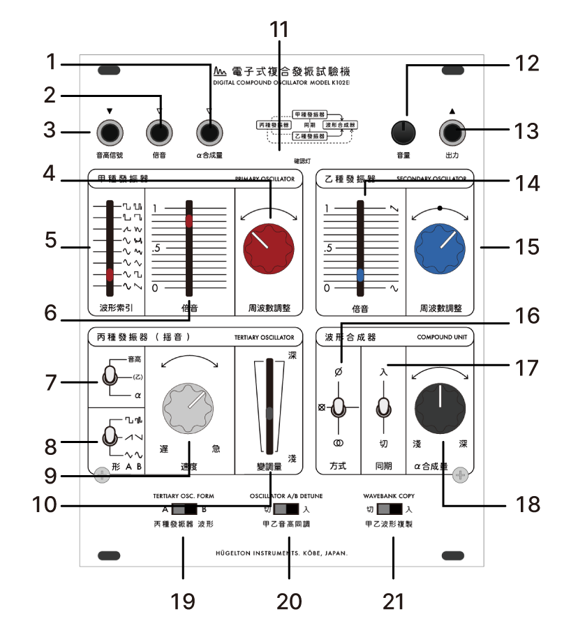
| No. | Name | Function |
|---|---|---|
| 1 | Pitch CV Input | V/Oct standard pitch control input |
| 2 | Harmonics Input | CV input for waveform read position |
| 3 | α Synthesis Input | CV input for synthesis parameter |
| 4 | Primary OSC Frequency | Main oscillator pitch adjustment |
| 5 | Waveform Selection | Wavetable selection |
| 6 | Harmonics Adjustment | Waveform read position adjustment |
| 7-10 | LFO Settings | Modulation destination/shape/rate/depth |
| 11-12 | Output Level | Signal level adjustment (attenuator) |
| 13 | Audio Output | Audio output (±5V) |
| 14-15 | Secondary OSC | Second oscillator harmonics/frequency |
| 16 | Synthesis Mode | PM/RM/Crossfade switching |
| 17 | Hard Sync | Primary → Secondary synchronization |
| 18 | α Amount | Manual synthesis parameter adjustment |
| 19-21 | Special Functions | Waveform AB/Tune/Copy switches |
Connection and Basic Operation
Installation Procedure
- Ensure Eurorack power is disconnected
- Verify bus cable orientation
- Install module and secure with mounting screws
Basic Operation
- Set output level to minimum during initial startup
- Adjust pitch of each oscillator
- Select desired waveforms
- Choose synthesis method and adjust alpha parameter
- Add modulation with LFO as needed
Precautions
- Always minimize output level when powering on/off
- Input signals within specified voltage range to CV inputs
- Make connections carefully to prevent damage from excessive input
- Use in environment with adequate ventilation